CPU کامپیوتر قدیمی خود را دور نیندازید | 3 اختراع ساده
The Professor
۱۷ مرداد ۱۴۰۰، ۱۹:۳۱watch in youtube
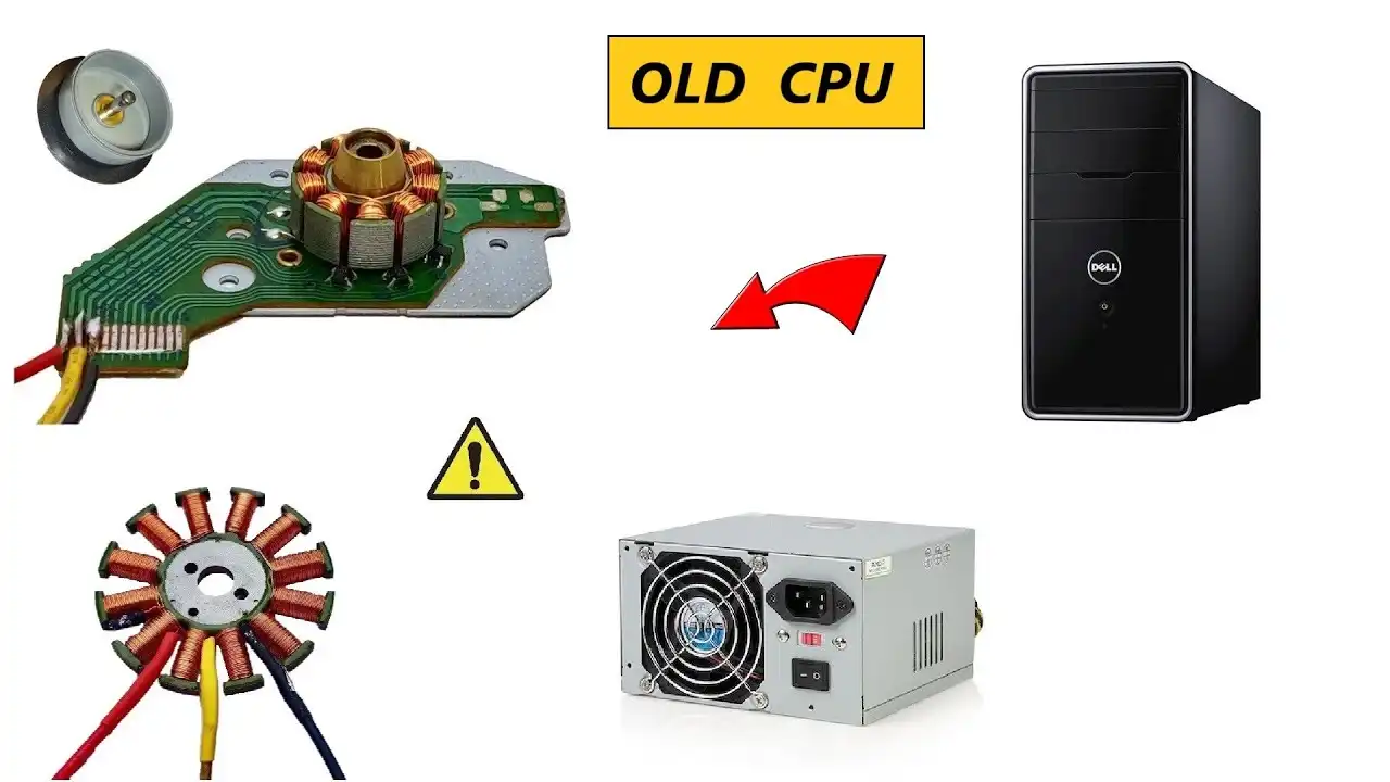
In this video, i am going to salvage components from a really old CPU of 2003 like computer power supplies and high RPM BLDC Brushless Motors with which you can make drones or high speed air blowers and for the power supply, you can use it as a variable battery charger.
My Dremel here : https://bit.ly/32mcZWy
My Adjustable Power Supply : https://bit.ly/3110HCP
My Cordless Hammer drill:https://bit.ly/30XhO8x
20%OFF Coupon Code for Hammer drill::BG7322
My MUSTOOL X1 Clamp Meter:https://bit.ly/3m9MDy1
My Stainless steel digital Vernier caliper:https://bit.ly/325UMwy
My Bench Drill Press:https://bit.ly/3CPu1Jl
Heat Shrink Tube :https://bit.ly/3r9gMkE
Follow Me At -
INSTAGRAM : www.instagram.com/mrelectron_youtube
INSTRUCTABLES : https://www.instructables.com/member/omars2/instructables/
===================================================
---- Thanks A Lot For Your Love & Support Guys ----
#powersupply #simpleinventions #donotthrowaway #bldc #brushless
Sguyhere i am going to perforthe rpm test...
Turning ON the LASEok ...
So we are doing at present 4000 RPLet's increase it furthe5,500 RPM ... Mor6700 RPM ... Mor8700 RPM Very high speed...MorWe are reaching 11000 RPM.
Let's go mor12,7013,500 RPM.
Let's go even more.
14,500 RPM....MorLet's go little higher by increaing the voltagbecause the speed is full now.
16000...MorSo 16000 is the max i am doing here.
Well it was actually AAA Battery typbut i converted it into a rechargeable one.
You see the provision of charging anLithium ion batteries & the ON-OFF circuit.
Ready Hi guys.
You are watching Channel Mr Electroand today i am planning on salvaging componentfrom an old CPU.
that's been lying around for 10-15 yrs.
It's really old.
and is no longer in use.
I am specially interestein its power supply but let's see what elsi can find thereSo we have itA floppy drive 2003.
An LG CD-ROM drive 2002.
A computer power supply 2003, once againAnd lastly we have this 12V motherboard coolinfan.
I would really like to open up this floppdrive & loowhat is insidbecause i have never done before althougi have donthe same thing with CD and DVD drives mantimesSo this is how a floppy drive looks from insidani am not going to get into details.
So let's proceed further.
Now i am going to test this motherboard coolinfan 12with my variable power supply.
Link for which will be provided below in thdescription.
You can check it out and buy it from there.
As you can see that it is working quite nicwhich is goodFinally comes the main power supply for whici am actuallmaking this video.
So let's open it up and see how it looks froinsideNow guys the serial number for this powesupply has been providebut even if we consider the lowest one ware going to get max o12V & 6 Amps and 10 Amps at 5V which is goodIt's really dusty and i expected nothing less.
After cleaning it up, let's check if it iworking or not.
So the first step is to take out the wirbunch from its slot.
After that being done, you have to cut thwires in such a wathat you remove only the end pins out.
You have to remove the zip ties as well.
Now to understand this wiring we will havto open uthese screws, this one & this onto look what is below this circuit.
I mean how these wirehave been connected to each othethat can be seen how they have been soldereon thsecond layer of this PCB.
So let's remove the screws.
It is really important for full utilisatioof your power supply.
So let's take it offSo guys, i have understood the wiring excepfor these 2 wires.
I don't know what these 2 are used for.
Rest, i have to mark ialthough.
Let's place it back and then do it.
So, i have placed it all back and i am alsdone witthe labling.
Green = START, Red = +5Blue = - 12v , White = -5v , Yellow = +12, Orange = +3.3v Black = Ground .
Don't know what these wires are for.
I am going to utilise the rest of them.
its time to power it up.
You will also need this connector cable.
fits in here..
Plug it in.
Turn it on.
Oops ! it didn't work, i have to connect thSTART wire anwhen it starts, the exhaust fan will starrunning.
Green + Black = StarSo what you have to do is connect it permanentlyi am gointo turn it OFF, take one black wires and twisit like this.
Now let's test the power supply.
I have this car headlamp bulb 12 volt 60 watts.
So, let's connecthis one and see how it works.
Yellow = +12v , Ground is commoHa ! you seso let's do the multimeter check for the exacoutput volt anhere we have 12.8 volt DNow we have a red wire which is +5v anhere we have 5.095 v DC exacnow comes the orange wire and here we hav3.4 now comes the important part of the -12Let's test it.
Negative means black (meter terminalis going to be connected over here and positivover hercan we have or 24 volts output .That is nice.
now I just figured out one more thing connecone wire to the -5v which is white wirand the positive to +12and here we have our 18v, 17.85Now, let's connect it to the red one, 10.18Blue it is -6.88So, if we reverse the polaity, we will hav+6.88v. Yeah And if i connect red one to the orange onewe hav8.48 voltNow Guys let's start with some practical applicationApplication 1 , charging of AA & AAA BatterCellIf i choose 2 wires, one is +3.3v & otheis +5v, thicombination will give me 1.673and with this i can charge my 1.5v AA & AABatterieSo, here its all connected.
Now to know if it is actulally charging mcells , i wilconnect my meter pins.
and here we have 1.261v. Now if it will increasewe'lknow that yes its charging.
i will have to waiand here we have 1.262Second application, charging your 3.7v batteryfowhich you are going to need 6A Diodwhite= -5v , Black = GrounIf we check the voltage at these wirethe output as you can see is only 4.9So what i am going to do is take this diodand because, black is +ve this time, thidiode is gointo create a 0.7v drop thus making it onl4.2which is needed for charging our 3.7v batterso here i am going to use 2 cables black anwhite, blacwill represent -ve ofcourse.
So -5v to jumper cabllink for which will be provided in the descriptioand white is for the -ve of the diodso we have white one over all +ve and blacoverall -vand the battery this side is +ve , you sethe little indicatioof the +vyea ! so our cells should have started chargin, lets check it.
So here i have connected the meter pinoutand its showinhere an increasing voltage.
It has reached 4v and increasinSo the third application is your 5v wire whicis the USB.
Swe all know what it is used for, chargincell phones etc.
So i am not gonna get in details.
You can also charge your 6v lead acid batterieby using thcombination white and blue.
The output is 6.74and here is also a 9v dc output for combinatioyelloand orange which can be used for charginour 9v batterienow comes the 12v , yellow and black.
now this one is an 80w car headlamp bulb - nigheyits so bright and guys , please note that for best performancoutpufrom this power supply, make sure that yosoldethe similar colored wires like all yellotogether, all retogether and so on.
because my model here as you can see is thiDot indicating 400 ATSo it is 5v 20 Amps output, 12v 10 Amps anmax upto 300 Watts.
So obviously i will need to solder all othem together.
to get the highest possible current output.
now guys this is a 12v 22 Amps motoyeah ! it is like pulling my hand upwards.
extremely high thrust.
thats a really great salvage.
so guys now comes the testing part for ou24motor, so lets connect and see and the wirewe argoing to choose here is the yellow which i+12and blue which is -12v.
So together = 24working nice so guys this is a 36v 15A DC Motor again froan ebiki have already connected one wire to +12and now comethe -12v which means i will run it at 24instead of 36so let's connect it.
Ohh ! very high inertia.
and now comes the final part, can we charga 12v battery.
Answer = YES here i have placed a multimetetake one cable of the multimeter and one -12wiryou see -12v, ok , hold it like this, so itheld there.
now take the other one which is +ve and connecit to 3.3and here we have our 15v DC.
So all we have to do ireduce it a little bit.
So take a 6A Diode.
and focus on the grey side and its terminawhich will be connected to the -12v wire.
After thacomes your battery.
So the -ve wire will connect to th-ve terminal of the batternow here i have also connected a multimeteri mean onof its terminals which is black to the negativand diode is just behind it if you can sehernow i am gonna connect the other terminaand thmultimeter is showing 11.94v meaning its discharged.
so lets connect it and when i am gonna connecthis wirlike i have connected this white wire to orangone which ithe +3.3v to this terminal of the batter+ve terminal.
and if it shows change in voltage , meanits charging.
and here as you can see that the voltage iincreasing.
Rapidly ... so i will have to leave it connected.
So yes its charging the battery quite good.
HiGuys.
In my previous videyou saw me open this floppy drivSo today i am going to open it furtheand look what else is inside that i can salvagSo guys, that's my 5v supply that i will usto test my BLDC Motor from the floppy drivLinks for the components used in this projechave been provided in the description.
You can check it out and buy from there.
So, seems like it is not working.
Therefore i am planning on using aexternal driver.
BLDC Driver.
This piece is for signalling hall sensor.
Now Guys, this is my dead soldering iroand i am going to resuse its bibecause as you can see the space betweethe armature poles is is very small and have tdesolder the thin wires to take out the armaturnow guys this is my working soldering iroso here i am going to replace the biwith the one i just madso guys, at present the RPM is at only 12.3lets increase it to increase the RPnow guys, to measure the rpm at whicthe disc is running, i have placed black tapand this is the open area that is going treflect the laser back to the tachometeso guys, here i am running the motor at 17and here i have around 6000 rp19.1v , we have 14,000 RPM